Episode 15 - What is a C.T?
Posted on Fri 01 March 2019 in Engineering • 2 min read
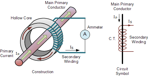
A C.T is the abbreviated form for a current transformer in electrical terms. It is a simple but effective use of magnetic circuits and transformer characteristics to monitor how power is behaving in a conductor. The C.T works by wrapping a coil of conductor around a core (typically silicon steel) shaped like a ring, the 'power' wire or the active is then passed through the core. When alternating current passes through the active conductor, this then generates a magnetic field around the wire, inducing a current proportional to the number of turns the wire is wrapped around the core.
The C.T is a very widely used piece of equipment in instrument electrical/electronics as it allows for an indirect way of monitoring for the power flow unlike a 'flow' meter that must be a part of the pipework to directly measure flow. While it is still possible to monitor current in a 'flow' meter type fashion, it is far less risk to implement a C.T solution.
Possibly the frequent implementation of C.Ts in everyday life is within power meter solutions. By attaching a C.T to the active conductor that is powering a piece of equipment, we are then able to measure the power the equipment is using in real time. This can then be further digitised and utilised in a network fashion to provide asset owners with real time energy usage of their equipment.
It must be noted when using C.Ts on alternating current systems that the C.T must only have a single conductor pass through it (the active); if both the active and the neutral are passed through the C.T then (in an ideal world) the C.T will have an output of 0. If you also pass through the earth wire to the equipment, it is possible to measure earth leakage or earth fault current (provided the measurement can handle it).
