Episode 11 - Power Quality Explained
Posted on Fri 01 February 2019 in Engineering • 5 min read
I've always lived by the rule that if you can't explain something to a 5 year old then you don't know it well enough. I was asked recently by some (non-electrical focused) colleagues on a handful of electrical terms and components. One of the biggest things that kept popping up that I found difficult to explain clearly was power quality and it's issues. So I decided why not dedicate a blog post about it and write a basic example power factor capacitor calculator in Python.
Power quality is defined as "the concept of powering and grounding sensitive electronic equipment in a manner suitable for the equipment with precise wiring system and other connected equipment" by the IEEE (The Institute of Electrical and Electronics Engineers). In a simplistic view this is just trying to say that electrical equipment is to be installed/configured in a way that is operates as intended.
Quality of power is not determined by the one who produces it, it's defined by the end user of the power. Eg, like a physical product, if you buy something from a store and it's poor quality, that's being defined by the end user. Similar to that of a physical product, quality of power can be lost in a variety of forms/ways.
Issues with power quality can be categorized into three main categories:
- Harmonic voltages and currents
- Poor power factor
- Voltage instability
Harmonics
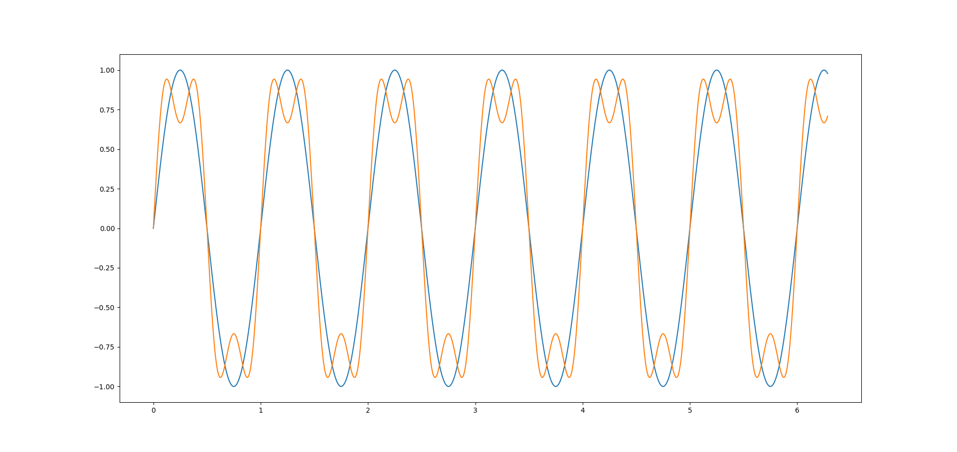
AC (Alternating Current) electricity is generated as a sinusoidal waveform, and harmonics are signals/waves whose frequency is a whole number multiple of the frequency of the reference signal/wave. To visualize this phenomenon, we can use packages like NumPy and Matplotlib, to calculate and plot our base signal and it's harmonics (I encourage you to run this code and change the harmonics to see what they look like).
1 2 3 4 5 6 7 8 9 10 11 12 13 14 15 16 17 18 | |
The example above shows us the base signal (fundamental frequency), and it's first harmonic (harmonic of 2 or twice as fast as the fundamental frequency).
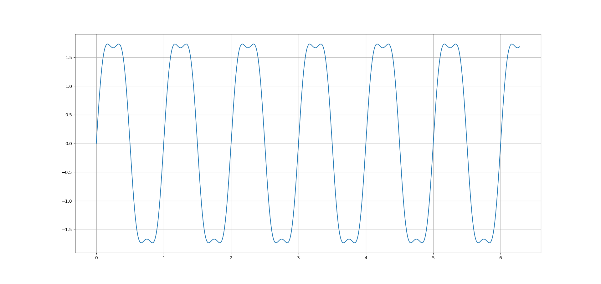
When these two signals are superimposed on each other, they produce a distorted waveform. Electrical equipment is designed to operate at the base signal (50Hz here in Australia), and typically does not cope with distorted wave like seen below when we superimpose a base signal with it's first harmonic.
Luckily, these issues are now easily detected and rectified by harmonic analyzers and active/passive harmonic filters.
Power Factor
Power factor is a measure of how effectively power is being used in an electrical system, and is defined as the ratio of real (useful) to apparent (total) power.
Real power (kW) is the power that actually powers the equipment to produce useful work (such as spinning a motor). It can also be called actual, active or working power.
Reactive power (kVAR) is the power required by (some) equipment (eg, motors), to produce a magnetic field to enable the useful work to be produce. It's necessary to operate the equipment, however you don't see any result from the reactive power.
Apparent power (kVA) is the vector sum of the real power (kW) and reactive power (kVAR) and is the total power supplied from the mains power required to produce the right amount of real power.
Suppose you are running a store, you have to spend an amount of money X (cost) on buying products to sell in the future for a larger amount of money Y, meaning your profit will be P = Y - X. X is not lost money, without spending X you will not be able to make any profit P. The profit P is comparable to the active power, the earnings Y are the equivalent of apparent power and the initial cost X is the reactive power.

Therefore, for a given power supply (kVA):
- The more cost you have (higher percentage of kVAR), the lower the ratio of kW (profit) to kVA (profit + cost), meaning a poorer power factor.
- The less cost you have (lower percentage of kVAR), the higher your ratio of kW (profit) to kVA (profit + cost) becomes, and the better you power factor. As your cost (kVAR) approaches zero, your power factor approaches 1 (unity).
Voltage Instability
A stable voltage is when every piece of equipment connected to a network is operating under normal condition without issues, however when a fault or disturbance (harmonics) occurs in this system, the voltage becomes unstable.
Due to voltage instability, the electrical system's voltage may collapse, if the voltage is below acceptable limits. Voltage collapse may be a total or partial black, the terms voltage instability and voltage collapse are interchangeable.
For example, if 10 generators are running to keep 10 machines working. Suddenly 3 of the generators run out of fuel, but the 10 machines keep going. This would cause a loss of generation, not being able to maintain the power required to keep all the machines working and consequentially since there is not enough power to share between any of the machines, all 10 machines will turn off, causing a total blackout.
Capacitor Calculator - Python
Correcting power factor from a lagging (\<1) power factor, can be as simple as reducing reactive power (kVAR) in the system such that the ratio of real power (kW) to apparent power (kVA) is still as close to unity (1) as possible.
Since motors require inductive or lagging power for magnetizing before useful work beings, this brings makes the power factor of the system lagging (\<1). Capacitors provide capacitive or leading reactive power that cancels out the lagging power when used for power-factor improvement. The improved power factor changes the current requirements of the system, but not the one required by the motor.


Using these formulas we can calculate just how big of a capacitor we require:


Once we input all these required formulas, and our initial data points, we are now able to easily compute the required size of capacitor to amend power factor issues.
1 2 3 4 5 6 7 8 9 10 11 12 13 14 15 16 17 18 19 20 21 22 23 24 25 26 27 28 29 30 31 32 33 34 35 | |